FRN0006C2S-7A in Vadodara |Fuji Electric FRN0006C2S-7A |FRN0006C2S-7A In India |FRN0006C2S-7A |S8VK-T12024 in Vadodara |OMRON S8VK-T12024 |S8VK-T12024 in India |NX1P2-1040-DT in Vadodara |NX1P2-1040-DT |CP1E-N40DR-A in Vadodaara |OMRON CP1E-N40DR-A |CP1E-N40DR-A in India |CP1E-N40DR-A |NB10W-TW01B in Vadodara |OMRON NB10W-TW01B |NB10W-TW01B |FVR0.4AS1S-7E in Vadodara |Fuji electric FVR0.4AS1S-7E |FVR0.4AS1S-7E in India |FRN0022E2S-4GBX in vadodara |Fuji Electric FRN0022E2S-4GBX |FRN0022E2S-4GBX in India |CP2E-N40DT1-D in Vadodara |CP2E-N40DT1-D In India |OMRON CP2E-N40DT1-D |CP2E-N40DT1-D |CJ1W-OD212 in Vadodara |OMRON CJ1W-OD212 |CJ1W-OD212 |E5CC-QX2ASM-802 OMI in Vadodara |OMRON E5CC-QX2ASM-802 OMI in Vadodara |E5CC-QX2ASM-802 OMI |FRN0290E2S-4GB In Vadodara |FRN0022E2S-4GBX In Vadodara |FRN0072E2S-4GBX In VADODARA |FRN0590E2S-4GB In Vadodara |FRN0590E2S-4GB In |E5CWL-Q1P In Vadodara |E5CWL-Q1P In India |E5DC-QX2ASM-802 In Vadodara |Omron Temperature controller |Omron E5DC In India |Omron E5CC In Gujarat |Omron E5CWL |FRN0203E2S-4GB In Vadodara |FRN0203E2S-4GB In India |FRN0012E2S-4GBX In Vadodara |TMH4-N2CB In Baroda |FRN0037E2S-4GBX In Vadodara |FRN0085E2S-4GB In Vadodara |FRN0105E2S-4GB In Vadodara |FRN0105E2S-4GB In India |FRN0240E2S-4GB In Vadodara |FRN0240E2S-4GB In India |FRN0168E2S-4GB In Vadodara |FRN0168E2S-4GB In India |E5CWL-R1TC In VADODARA |E5CWL-R1TC In India |E5DC-QX2ASM-002 In Vadodara |FRN0004E2S-4GB In Vadodara |FRN0004E2S-4GB In India |FRN0139E2S-4GB In VADODARA |FRN0139E2S-4GB In India |Usb To 485 Modbus Converter |RS 485 To Modbus Converter |FRN0006E2S-4GB In VADODARA |TX4S-14R In Vadodara |TX4S-14R In India |Fuji Servo Surat |Fuji Servo Supplier |Fuji servo Support Near Me |Fuji Dealer In Gujarat |Fuji Dealer In Baroda |FRN0059E2S-4GBX In Vadodara |FRN0059E2S-4GBX In India |FRN0044E2S-4GBX In Vadodara |E5CC-QX2ASM-000 In Vadodara |FRN0007E2S-4GB In Vadodara |TX4S-24S In Vadodara |TX4S-24S In India |FRN0002E2S-4GB In Vadodara |FRN0415E2S-4GB In Vadodara |FRN0520E2S-4GB In Vadodara |FRN0520E2S-4GB In India |TCN4S-24R In Vadodara |FRN0361E2S-4GB In Vadodara |FRN0361E2S-4GB In India |SRB402EM In Vadodara |SRB402EM (SCHMERSAL MAKE) In India |PS/1AC/24VDC/120W/EE (P2910586) In Vadodara |PS/1AC/24VDC/120W/EE (P2910586) In India |VFD9A0MS43ANSAA In Vadodara |VFD9A0MS43ANSAA In India |VFD32AMS43ANSAA In Vadodara |VFD32AMS43ANSAA In India |PS/1AC/24VDC/240W/EE (P2910587) In Vadodara |PS/1AC/24VDC/240W/EE (P2910587) In India |PS-3AC/24DC/960/EE (1018294) In Vadodara |PS-3AC/24DC/960/EE (1018294) In India |VFD4A2MS43ANSAA In Vadodara |K3HB-VLC-L2BT11 In VADODARA |K3HB-VLC-L2BT11 OMRON In India |VFD13AMS43ANSAA In Vadodara |VFD13AMS43ANSAA In India |VFD17AMS43ANSAA In Vadodara |VFD17AMS43ANSAA In India |VFD5A5MS43ANSAA In VADODARA |VFD25AMS43ANSAA In Vadodara |VFD25AMS43ANSAA In India |SRB-E-301MC (SCHMERSAL SAFETY RELAY) In India |SRB-E-301MC (SCHMERSAL SAFETY RELAY) In Vadodara |SRB301MC-24V In Vadodara |SRB301MC-24V In India |K3HB-VLC-L1B1-502-AC/DC24 In Vadodara |K3HB-VLC-L1B1-502-AC/DC24 In India |VFD38AMS43ANSAA In Vadodara |VFD38AMS43ANSAA In India |VFD2A7MS43ANSAA In Vadodara |SRB324ST 24V In Vadodara |SRB324ST 24V In India |ZEN-20C1DR-D-V2 In Vadodara |OMRON PLC ZEN-20C1DR-D-V2 In India |PS/1AC/24DC/480W/EE (2910588) In VADODARA |PS/1AC/24DC/480W/EE (2910588) In India |SRB-E-301ST In Vadodara |SRB-E-301ST In India |IB IL AI 4/U/0-10-ECO In VADODARA |IB IL AI 4/U/0-10-ECO In India |IB IL 24 DI 32/HD-NPN-PAC In Vadodara |IB IL 24 DI 32/HD-NPN-PAC In India |IL EC BK-PAC In Vadodara |IL EC BK-PAC In India |IL EIP BK DI8 DO4 2TX-PAC In Vadodara |IL EIP BK DI8 DO4 2TX-PAC In India |AXL SE AO4 U 0-10 In Vadodara |AXL SE AO4 U 0-10 In India |IB IL AO 4/U/0-10-ECO In India |IB IL AO 4/U/0-10-ECO In VADODARA |IB IL 24 DI 16-PAC In Vadodara |IB IL 24 DI 16-PAC In India |Limit switch in India |Limit switch supplier in Vadodara |Power Supply in India |Power supply supplier in vadodara |Power Supply supplier in vadodara |CABLE PULL SWITCH in India |CABLE PULL SWITCH supplier in Vadodara |SRB-E-301MC (SCHMERSAL SAFETY RELAY) In Vadodara |Safety Interlock Switch in India |Safety Interlock Switch supplier in Vadodara |POSITION SWITCH in India |POSITION SWITCH supplier in Vadodara |SAFETY SENSOR in India |SAFETY SENSOR supplier in Vadodara |Safety relay in India |Safety relay supplier in Vadodara |Safety switch in India |Safety switch supplier in Vadodara |Safety Light Curtain in India |Safety Light Curtain supplier in Vadodara |SOLENOID INTERLOCK in India |SOLENOID INTERLOCK Supplier in Vadodara |Safety actuator in India |ACTUATOR supplier in Vadodara |SAFTEY SENSOR in India |SAFTEY SENSOR Supplier in Vadodara |Safety contacts in India |Safety contacts supplier in Vadodara |Connector Cables in India |Connector Cables supplier in Vadodara |SAFETY SENSOR in India |SAFETY SENSOR Supplier in Vadodara |SAFETY SENSOR supplier in Vadodara |Limit Switch in India |safety controller in India |safety controller supplier in vadodara |Interlock device in India |Interlock device supplier in Vadodara |ACTUATOR in india |A-K5P-M12-S-G-5M-BK-1-X-A-1 In Vadodara |A-K5P-M12-S-G-5M-BK-1-X-A-1 In India |SAFTEY SWITCH in India |SAFTEY SWITCH supplier in Vadodara |TZ/CO IN VADODARA |TZ/CO IN INDIA |POSITION SWITCH in Vadodara |TZFCWS24VDC-2917 In Vadodara |TZFCWS24VDC-2917 In India |ACTUATOR AZ 17-B6 In Vadodara |ACTUATOR AZ 17-B6 In India |SLC440COM-ER-1450-30 In Vadodara |SLC440COM-ER-1450-30 In India |Limit Switch supplier in Vadodara |M6-TENSIONING JACK-SS316 In Vadodara |M6-TENSIONING JACK-SS316 In India
LADDERLOGIX Products
919537882136
Chat with us 

This is your website preview.
Currently it only shows your basic business info. Start adding relevant business details such as description, images and products or services to gain your customers attention by using Boost 360 android app / iOS App / web portal.
Manufacturing test
Home  Products

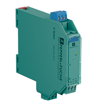
![1-channel isolated barrier24 V DC supply (Power Rail)Dry contact or NAMUR inputsUsable as signal splitter (1 input and 2 outputs)Relay contact outputFault relay contact outputLine fault detection (LFD)Housing width 12.5 mmUp to SIL 2 acc. to IEC/EN 61508General specificationsSignal type Digital InputFunctional safety related parametersSafety Integrity Level (SIL) SIL 2SupplyConnection Power Rail or terminals 9+, 10-Rated voltage 19 ... 30 V DCRipple ≤ 10 %Rated current ≤ 37 mAPower dissipation ≤ 750 mWPower consumption ≤ 750 mWInputConnection side field sideConnection terminals 1+, 2-Rated values acc. to EN 60947-5-6 (NAMUR)Open circuit voltage/short-circuit current approx. 8 V DC / approx. 8 mASwitching point/switching hysteresis 1.2 ... 2.1 mA / approx. 0.2 mALine fault detection breakage I ≤ 0.1 mA , short-circuit I ≥ 6.5 mAPulse/Pause ratio min. 20 ms / min. 20 msOutputConnection side control sideConnection output I: terminals 5, 6 ; output II: terminals 7, 8Output I signal ; relayOutput II signal or error message ; relayContact loading 250 V AC/2 A/cos φ > 0.75; 126.5 V AC/4 A/cos φ > 0.75; 30 V DC/2 A resistive loadMinimum switch current 2 mA / 24 V DCEnergized/De-energized delay ≤ 20 ms / ≤ 20 msMechanical life 107 switching cyclesTransfer characteristicsSwitching frequency ≤ 10 HzGalvanic isolationInput/Output reinforced insulation according to IEC/EN 61010-1, rated insulation voltage 300 VeffInput/power supply reinforced insulation according to IEC/EN 61010-1, rated insulation voltage 300 VeffOutput/power supply reinforced insulation according to IEC/EN 61010-1, rated insulation voltage 300 VeffOutput/Output reinforced insulation according to IEC/EN 61010-1, rated insulation voltage 300 VeffIndicators/settingsDisplay elements LEDsControl elements DIP switchConfiguration via DIP switchesLabeling space for labeling at the frontDirective conformityElectromagnetic compatibility Directive 2014/30/EU EN 61326-1:2013 (industrial locations)Low voltage Directive 2014/35/EU EN 61010-1:2010+A1:2019+A1:2019/AC:2019ConformityElectromagnetic compatibility NE 21:2017 , EN 61326-3-1:2017 , EN IEC 61326-3-2:2018Degree of protection IEC 60529:1989+A1:1999+A2:2013Functional safety IEC/EN 61508:2010Input EN 60947-5-6:2000Ambient conditionsAmbient temperature -40 ... 70 °C (-40 ... 158 °F)Mechanical specificationsDegree of protection IP20Connection screw terminalsMass approx. 100 gDimensions 12.5 x 119 x 114 mm (0.5 x 4.7 x 4.5 inch) (W x H x D) , housing type A2Mounting on 35 mm DIN mounting rail acc. to EN 60715:2001Data for application in connection with hazardous areasEU-type examination certificate BASEEFA 06 ATEX 0092 XMarking Ex-Hexagon II 3(1)G Ex ec nC [ia Ga] IIC T4 Gc , Ex-Hexagon II (1)D [Ex ia Da] IIIC , Ex-Hexagon I (M1) [Ex ia Ma] IInput Ex iaVoltage 10.5 VCurrent 13 mAPower 34 mW (linear characteristic)Supply Maximum safe voltage 253 V AC (Attention! Um is no rated voltage.)Output Contact loading Zone 2 : 50 V AC/2 A/cos φ > 0.75; 30 V DC/2 A resistive loadMaximum safe voltage 253 V AC (Attention! The rated voltage can be lower.)Fault indication output Maximum safe voltage 40 V DC (Attention! Um is no rated voltage.)Galvanic isolation Input/Output safe electrical isolation acc. to IEC/EN 60079-11, voltage peak value 375 VInput/power supply safe electrical isolation acc. to IEC/EN 60079-11, voltage peak value 375 VDirective conformity Directive 2014/34/EU EN IEC 60079-0:2018 , EN 60079-7:2015+A1:2018 , EN 60079-11:2012 , EN IEC 60079-15:2019International approvalsUL approval E106378Control drawing 116-0477 (cULus)IECEx approval IECEx certificate IECEx BAS 06.0025 XIECEx marking Ex ec nC [ia Ga] IIC T4 Gc[Ex ia Da] IIIC[Ex ia Ma] I](https://productimages.withfloats.com/tile/635e135fc7b01e0001eb35f1.jpg)
KCD2-SR-Ex1.LB
VIEW DETAILS
![1-channel isolated barrier24 V DC supply (Power Rail)Dry contact or NAMUR inputsUsable as signal splitter (1 input and 2 outputs)Relay contact outputFault relay contact outputLine fault detection (LFD)Reversible mode of operationUp to SIL 2 acc. to IEC 61508/IEC 61511General specificationsSignal type Digital InputFunctional safety related parametersSafety Integrity Level (SIL) SIL 2SupplyConnection Power Rail or terminals 14+, 15-Rated voltage 19 ... 30 V DCRipple ≤ 10 %Rated current ≤ 45 mAPower dissipation ≤ 0.9 WPower consumption ≤ 0.9 WInputConnection side field sideConnection terminals 1+, 2+, 3-Rated values acc. to EN 60947-5-6 (NAMUR)Open circuit voltage/short-circuit current approx. 8 V DC / approx. 8 mASwitching point/switching hysteresis 1.2 ... 2.1 mA / approx. 0.2 mALine fault detection breakage I ≤ 0.1 mA , short-circuit I > 6 mAPulse/Pause ratio min. 20 ms / min. 20 msOutputConnection side control sideConnection output I: terminals 7, 8, 9 ; output II: terminals 10, 11, 12Output I signal ; relayOutput II signal or fault message ; relayContact loading 250 V AC/2 A/cos φ > 0.75; 126.5 V AC/4 A/cos φ > 0.75; 40 V DC/2 A resistive loadMinimum switch current 2 mA / 24 V DCEnergized/De-energized delay approx. 20 ms / approx. 20 msMechanical life 107 switching cyclesCollective error message Power RailTransfer characteristicsSwitching frequency ≤ 10 HzGalvanic isolationInput/Output reinforced insulation according to IEC/EN 61010-1, rated insulation voltage 300 VeffInput/power supply reinforced insulation according to IEC/EN 61010-1, rated insulation voltage 300 VeffOutput/power supply reinforced insulation according to IEC/EN 61010-1, rated insulation voltage 300 VeffOutput/Output reinforced insulation according to IEC/EN 61010-1, rated insulation voltage 300 VeffIndicators/settingsDisplay elements LEDsControl elements DIP switchConfiguration via DIP switchesLabeling space for labeling at the frontDirective conformityElectromagnetic compatibility Directive 2014/30/EU EN 61326-1:2013 (industrial locations)Low voltage Directive 2014/35/EU EN 61010-1:2010+A1:2019+A1:2019/AC:2019ConformityElectromagnetic compatibility NE 21:2017 , EN 61326-3-1:2017 , EN IEC 61326-3-2:2018Degree of protection IEC 60529:1989+A1:1999+A2:2013Functional safety IEC/EN 61508:2010Input EN 60947-5-6:2000Ambient conditionsAmbient temperature -20 ... 70 °C (-4 ... 158 °F)Mechanical specificationsDegree of protection IP20Connection screw terminalsMass approx. 150 gDimensions 20 x 119 x 115 mm (0.8 x 4.7 x 4.5 inch) (W x H x D) , housing type B2Mounting on 35 mm DIN mounting rail acc. to EN 60715:2001Data for application in connection with hazardous areasEU-type examination certificate PTB 00 ATEX 2080Marking Ex-Hexagon II (1)G [Ex ia Ga] IICEx-Hexagon II (1)D [Ex ia Da] IIICEx-Hexagon I (M1) [Ex ia Ma] IInput Ex iaVoltage 10.5 VCurrent 13 mAPower 34 mW (linear characteristic)Supply Maximum safe voltage 253 V AC / 125 V DC (Attention! Um is no rated voltage.)Output Maximum safe voltage 253 V AC (Attention! The rated voltage can be lower.)Fault indication output Maximum safe voltage 40 V DC (Attention! Um is no rated voltage.)Certificate PF 08 CERT 0803Marking Ex-Hexagon II (3)G [Ex ic Gc] IICInput Ex icVoltage 10.5 VCurrent 13 mAPower 34 mW (linear characteristic)Certificate TÜV 99 ATEX 1493 XMarking Ex-Hexagon II 3G Ex ec nC IIC T4 GcGalvanic isolation Input/Output safe electrical isolation acc. to IEC/EN 60079-11, voltage peak value 375 VInput/power supply safe electrical isolation acc. to IEC/EN 60079-11, voltage peak value 375 VDirective conformity Directive 2014/34/EU EN IEC 60079-0:2018+AC:2020 , EN 60079-7:2015+A1:2018 , EN 60079-11:2012 , EN IEC 60079-15:2019International approvalsFM approval FM certificate FM19US0207XControl drawing 116-0035UL approval E106378Control drawing 116-0473 (cULus)Contact loading 250 V AC/2 A/cos φ > 0.75; 126.5 V AC/4 A/cos φ > 0.75; 30 V DC/2 A resistive loadIECEx approval IECEx certificate IECEx PTB 11.0034 , IECEx TUN 19.0013XIECEx marking [Ex ia Ga] IIC[Ex ia Da] IIIC[Ex ia Ma] IEx ec nC IIC T4 Gc](https://productimages.withfloats.com/tile/635e12405d8f8c0001fd0509.png)
KFD2-SR2-Ex1.W.LB
VIEW DETAILS
![1-channel isolated barrier24 V DC supply (Power Rail)Input for 2-wire SMART transmitters and current sourcesSignal splitter (1 input and 2 outputs)Dual output 0/4 mA ... 20 mA or 0/1 V ... 5 VTerminal blocks with test socketsSIL 2 (SC 3) acc. to IEC/EN 61508General specificationsSignal type Analog inputFunctional safety related parametersSafety Integrity Level (SIL) SIL 2Systematic capability (SC) SC 3SupplyConnection Power Rail or terminals 9+, 10-Rated voltage 19 ... 30 V DCRipple within the supply tolerancePower dissipation approx. 1.4 W at 20 mA transfer current, 250 Ω in both outputsPower consumption 2 WInputConnection side field sideConnection terminals 1+, 2- (sink); 3+, 4- (source)Input signal 0/4 ... 20 mAVoltage drop terminals 3, 4: ≤ 6.1 V at 20 mAShort-circuit current terminals 1+, 2-: 25 mAInput resistance terminals 1+, 2-: max. 500 Ω (BRAIN)(250 Ω load)Available voltage terminals 1+, 2-: ≥ 16 V at 20 mA , ≥ 18.5 V at 4 mAOutputConnection side control sideConnection source: terminals 5-, 6+; 7-, 8+sink: terminals 5+, 6-, 7+, 8-Load channel 1: 0 ... 500 Ω (20 mA)/> 1 MΩ (5 V)channel 2: 0 ... 500 Ω (20 mA)/> 1 MΩ (5 V)Output signal 0/4 ... 20 mA or 0/1 ... 5 VRipple max. 50 µA rmsTransfer characteristicsDeviation Iout < 20 µA (0.1 %); Vout < 10 mV (0.2 %) incl. calibration, linearity, hysteresis and fluctuation of supply voltage, at 20 °C (68 °F), 0/4 ... 20 mA, 0/1 ... 5 VInfluence of ambient temperature current output: 0.25 µA/Kvoltage output: 80 µV/KFrequency range field side into the control side: bandwidth with 0.5 Vpp signal 0 ... 6 kHz (-3 dB)control side into the field side: bandwidth with 0.5 Vpp signal 0.3 ... 6 kHz (-3 dB)Settling time 6 msRise time/fall time 2 msGalvanic isolationOutput/power supply functional insulation, rated insulation voltage 50 V ACOutput/Output functional insulation, rated insulation voltage 50 V ACIndicators/settingsDisplay elements LEDControl elements DIP switchConfiguration via DIP switchesLabeling space for labeling at the frontDirective conformityElectromagnetic compatibility Directive 2014/30/EU EN 61326-1:2013 (industrial locations)ConformityElectromagnetic compatibility NE 21:2012EN 61326-3-2:2008Degree of protection IEC 60529:2001Protection against electrical shock UL 61010-1:2012Ambient conditionsAmbient temperature -20 ... 60 °C (-4 ... 140 °F)extended ambient temperature range up to 70 °C (158 °F), refer to manual for necessary mounting conditionsMechanical specificationsDegree of protection IP20Connection screw terminalsMass approx. 100 gDimensions 12.5 x 124 x 114 mm (0.5 x 4.9 x 4.5 inch) (W x H x D) , housing type A2Mounting on 35 mm DIN mounting rail acc. to EN 60715:2001Data for application in connection with hazardous areasEU-type examination certificate BASEEFA 13 ATEX 0077 XMarking Ex-Hexagon II (1)G [Ex ia Ga] IICEx-Hexagon II (1)D [Ex ia Da] IIICEx-Hexagon I (M1) [Ex ia Ma] IInput [Ex ia Ga] IIC, [Ex ia Da] IIIC, [Ex ia Ma] ISupply Maximum safe voltage 250 V (Attention! The rated voltage can be lower.)Equipment terminals 1+, 2-Voltage 25.2 VVoltage 28.2 VCurrent 93 mAPower 656 mWInternal capacitance 10 nFInternal inductance 0 mHEquipment terminals 3+, 4-Voltage 30 VCurrent 115 mAPower 700 mWVoltage 5 VCurrent 6.8 mAPower 1.6 mWOutput Maximum safe voltage 250 V (Attention! The rated voltage can be lower.)Certificate BASEEFA 13 ATEX 0078 XMarking Ex-Hexagon II 3G Ex nA II T4 Gc [device in zone 2]Galvanic isolation Input/Output safe electrical isolation acc. to IEC/EN 60079-11, voltage peak value 375 VInput/power supply safe electrical isolation acc. to IEC/EN 60079-11, voltage peak value 375 VDirective conformity Directive 2014/34/EU EN 60079-0:2012+A11:2013 , EN 60079-11:2012 , EN 60079-15:2010International approvalsUL approval Control drawing 116-0380 (cULus)IECEx approval IECEx certificate IECEx BAS 13.0043XIECEx marking [Ex ia Ga] IIC, [Ex ia Da] IIIC, [Ex ia Ma] I](https://productimages.withfloats.com/tile/635e110be52a05000198bd1d.jpg)
KCD2-STC-Ex1.2O
VIEW DETAILS
![1-channel isolated barrier24 V DC supply (Power Rail)Input 2-wire and 3-wire SMART transmitters and 2-wire SMART current sourcesSignal splitter (1 input and 2 outputs)Dual output 4 mA ... 20 mA current sink/current sourceTerminals with test pointsSIL 2 (SC 3) acc. to IEC/EN 61508General specificationsSignal type Analog inputFunctional safety related parametersSafety Integrity Level (SIL) SIL 2Systematic capability (SC) SC 3SupplyConnection Power Rail or terminals 14+, 15-Rated voltage 18 ... 30 V DCRipple within the supply tolerancePower dissipation ≤ 1 W at maximum loadPower consumption ≤ 1.7 W at maximum loadInputConnection side field sideConnection terminals 1+, 2-, 3Input signal 4 ... 20 mAOpen circuit voltage/short-circuit current terminals 1+, 3: 23 V / 25 mAInput resistance max. 265 Ω terminals 2-, 3 , max. 330 Ω terminals 1+, 3Available voltage ≥ 16 V at 20 mA ; ≥ 20 V at 4 mA , terminals 1+, 3OutputConnection side control sideConnection terminals 7+, 8-, 9-; 10+, 11-, 12- (sink)terminals 7-, 8+, 9+; 10-, 11+, 12+ (source)see additional informationLoad 0 ... 600 ΩOutput signal 4 ... 20 mA (overload > 25 mA)Ripple max. 50 µA rmsExternal supply (loop) 2 ... 30 V DCIf the external voltage is > 19 V, a load ≥ ((V - 19) / 0.02) Ω is required. V represents the value of the external voltage.The internal 250 Ω resistor at terminals 9 and 12 can be used as a load.Transfer characteristicsDeviation at 20 °C (68 °F), 4 ... 20 mA≤ 10 µA incl. calibration, linearity, hysteresis, loads and fluctuations of supply voltageInfluence of ambient temperature ≤ 0.25 µA/KFrequency range field side into the control side: bandwidth with 0.5 Vpp signal 0 ... 7.5 kHz (-3 dB)control side into the field side: bandwidth with 0.5 Vpp signal 0.3 ... 7.5 kHz (-3 dB)Settling time 200 µsRise time/fall time 100 µsGalvanic isolationOutput/power supply functional insulation, rated insulation voltage 50 V ACOutput/Output functional insulation, rated insulation voltage 50 V ACIndicators/settingsDisplay elements LEDLabeling space for labeling at the frontDirective conformityElectromagnetic compatibility Directive 2014/30/EU EN 61326-1:2013 (industrial locations)ConformityElectromagnetic compatibility NE 21:2012EN 61326-3-2:2008Degree of protection IEC 60529:2001Protection against electrical shock UL 61010-1:2012Ambient conditionsAmbient temperature -20 ... 60 °C (-4 ... 140 °F)extended ambient temperature range up to 70 °C (158 °F), refer to manual for necessary mounting conditionsMechanical specificationsDegree of protection IP20Connection screw terminalsMass approx. 200 gDimensions 20 x 124 x 115 mm (0.8 x 4.9 x 4.5 inch) (W x H x D) , housing type B2Mounting on 35 mm DIN mounting rail acc. to EN 60715:2001Data for application in connection with hazardous areasEU-type examination certificate CML 17 ATEX 2031XMarking Ex-Hexagon II (1)G [Ex ia Ga] IICEx-Hexagon II (1)D [Ex ia Da] IIICEx-Hexagon I (M1) [Ex ia Ma] IInput [Ex ia Ga] IIC, [Ex ia Da] IIIC, [Ex ia Ma] ISupply Maximum safe voltage 250 V (Attention! The rated voltage can be lower.)Equipment terminals 1+, 3-Voltage 26.2 VVoltage 27.25 VCurrent 93 mAPower 634 mWEquipment terminals 2-, 3Voltage 30 VCurrent 115 mAPower max 1 WVoltage 2 VCurrent 8.5 mAPower 4.3 mWEquipment terminals 1+, 2 / 3-Voltage 26.2 VVoltage 27.25 VCurrent 115 mAPower 784 mWCertificate CML 17 ATEX 3030XMarking Ex-Hexagon II 3G Ex ec IIC T4 GcGalvanic isolation Input/Output safe electrical isolation acc. to IEC/EN 60079-11:2007, voltage peak value 375 VInput/power supply safe electrical isolation acc. to IEC/EN 60079-11:2007, voltage peak value 375 VDirective conformity Directive 2014/34/EU EN IEC 60079-0:2018+AC:2020 , EN 60079-7:2015+A1:2018 , EN 60079-11:2012International approvalsUL approval E106378Control drawing 116-0439 (cULus)IECEx approval IECEx certificate IECEx CML 17.0016XIECEx marking [Ex ia Ga] IIC , [Ex ia Da] IIIC , [Ex ia Ma] IEx ec IIC T4 Gc](https://productimages.withfloats.com/tile/635e0f910c93040001f7c338.jpg)
KFD2-STC5-Ex1.2O
VIEW DETAILS
![1-channel isolated barrier24 V DC supply (Power Rail)Input for 2-wire SMART transmitters and current sourcesOutput for 4 mA ... 20 mA or 1 V ... 5 VHousing width 12.5 mmSIL 2 (SC 3) acc. to IEC/EN 61508General specificationsSignal type Analog inputFunctional safety related parametersSafety Integrity Level (SIL) SIL 2Systematic capability (SC) SC 3SupplyConnection Power Rail or terminals 9+, 10-Rated voltage 19 ... 30 V DCRipple ≤ 10 %Rated current ≤ 45 mA at 24 V and 20 mA source mode outputPower dissipation ≤ 800 mWPower consumption ≤ 1.1 WInputConnection side field sideConnection terminals 1+, 2-; 3+, 4-Input signal 4 ... 20 mA limited to approx. 26 mAOpen circuit voltage/short-circuit current terminals 1+, 2-: 22 V / 26 mAVoltage drop terminals 3+, 4- : approx. 5 VAvailable voltage terminals 1+, 2-: ≥ 15 V at 20 mA ; ≥ 18 V at 4 mAOutputConnection side control sideConnection terminals 5-, 6+terminals 5-, 8+ for HART resistorLoad 0 ... 350 Ω (source mode)Output signal 4 ... 20 mA or 1 ... 5 V (on 250 Ω, 0.1 % internal shunt)4 ... 20 mA (sink mode), operating voltage 10 ... 30 VRipple 20 mV rmsTransfer characteristicsDeviation at 20 °C (68 °F)< 0.1 % of full scale, incl. non-linearity and hysteresis (source mode and sink mode 4 ... 20 mA)≤ ± 0.2 % incl. non-linearity and hysteresis (source mode 1 ... 5 V)Influence of ambient temperature < 2 µA/K (-20 ... 70 °C (-4 ... 158 °F)); < 4 µA/K (-40 ... -20 °C (-40 ... -4 °F)) (source mode and sink mode 4 ... 20mA)< 0.5 mV/K (-20 ... 70 °C (-4 ... 158 °F)); < 1 mV/K (-40 ... -20 °C (-40 ... -4 °F)) (source mode 1...5 V)Frequency range field side into the control side: bandwidth with 0.5 Vpp signal 0 ... 3 kHz (-3 dB)control side into the field side: bandwidth with 0.5 Vpp signal 0 ... 3 kHz (-3 dB)Settling time ≤ 50 msRise time/fall time ≤ 10 msGalvanic isolationInput/Output basic insulation according to IEC/EN 61010-1, rated insulation voltage 300 VeffInput/power supply reinforced insulation according to IEC/EN 61010-1, rated insulation voltage 300 VeffOutput/power supply basic insulation according to IEC/EN 61010-1, rated insulation voltage 300 VeffIndicators/settingsDisplay elements LEDControl elements DIP switchConfiguration via DIP switchesLabeling space for labeling at the frontDirective conformityElectromagnetic compatibility Directive 2014/30/EU EN 61326-1:2013 (industrial locations)ConformityElectromagnetic compatibility NE 21:2017EN 61326-3-2:2018Degree of protection IEC 60529:2001Protection against electrical shock UL 61010-1:2012Ambient conditionsAmbient temperature -40 ... 70 °C (-40 ... 158 °F)Mechanical specificationsDegree of protection IP20Connection screw terminalsMass approx. 100 gDimensions 12.5 x 119 x 114 mm (0.5 x 4.7 x 4.5 inch) (W x H x D) , housing type A2Mounting on 35 mm DIN mounting rail acc. to EN 60715:2001Data for application in connection with hazardous areasEU-type examination certificate CESI 06 ATEX 021Marking Ex-Hexagon II (1)G [Ex ia Ga] IICEx-Hexagon II (1)D [Ex ia Da] IIICEx-Hexagon I (M1) [Ex ia Ma] IInput Ex iaSupply Maximum safe voltage 250 V AC (Attention! Um is no rated voltage.)Equipment terminals 1+, 2-Voltage 25.2 VCurrent 100 mAPower 630 mWInternal capacitance 5.7 nFInternal inductance negligibleEquipment terminals 3+, 4-Voltage 30 VCurrent 128 mAVoltage 7.2 VCurrent 100 mAPower 25 mWInternal capacitance 5.7 nFInternal inductance negligibleCertificate CESI 19 ATEX 021 XMarking Ex-Hexagon II 3G Ex ec IIC T4 GcGalvanic isolation Input/Output safe electrical isolation acc. to IEC/EN 60079-11, voltage peak value 375 VInput/power supply safe electrical isolation acc. to IEC/EN 60079-11, voltage peak value 375 VDirective conformity Directive 2014/34/EU EN 60079-0:2012+A11:2013 , EN 60079-11:2012 , EN 60079-7:2015International approvalsFM approval FM certificate FM 18 CA 0116 X , FM 19 US 0117 XControl drawing 116-0469 (cFMus)UL approval E106378Control drawing 116-0459 (cULus)IECEx approval IECEx certificate IECEx CES 06.0001XIECEx marking [Ex ia Ga] IIC , [Ex ia Da] IIIC , [Ex ia Ma] IEx ec IIC T4 Gc](https://productimages.withfloats.com/tile/635e0b97bb77e100018dfb6c.jpg)
KCD2-STC-Ex1
VIEW DETAILS
KFD2-STC5-Ex1
VIEW DETAILS
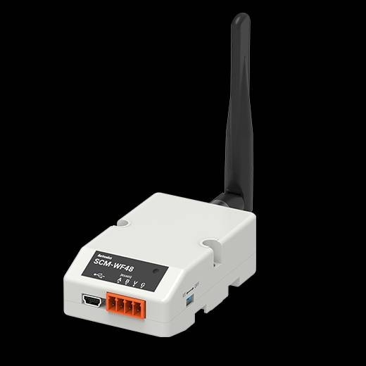
USB To Modbus Converter
VIEW DETAILS
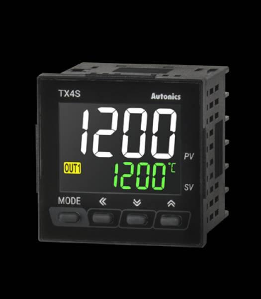
TX4S-24S
VIEW DETAILS
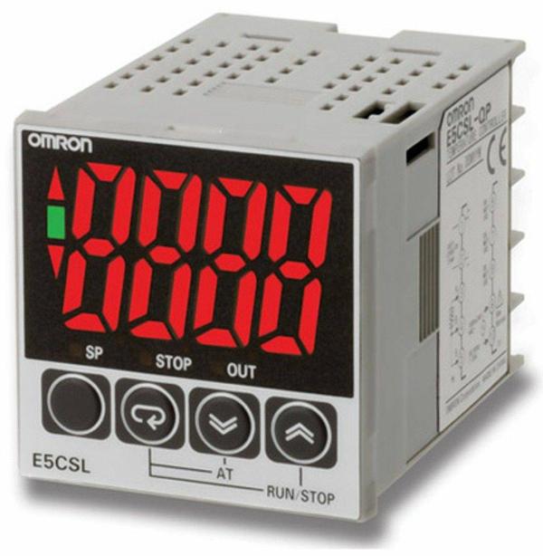
E5CWL-Q1P
VIEW DETAILS

E5CWL-R1TC
VIEW DETAILS
E5CWL-Q1TC
VIEW DETAILS
TX4S-14R
VIEW DETAILS
Filter using tags
FRN0006C2S-7A in VadodaraFuji Electric FRN0006C2S-7AFRN0006C2S-7A In IndiaFRN0006C2S-7AS8VK-T12024 in VadodaraOMRON S8VK-T12024S8VK-T12024 in IndiaNX1P2-1040-DT in VadodaraNX1P2-1040-DTCP1E-N40DR-A in VadodaaraOMRON CP1E-N40DR-ACP1E-N40DR-A in IndiaCP1E-N40DR-ANB10W-TW01B in VadodaraOMRON NB10W-TW01BNB10W-TW01BFVR0.4AS1S-7E in VadodaraFuji electric FVR0.4AS1S-7EFVR0.4AS1S-7E in IndiaFRN0022E2S-4GBX in vadodaraFuji Electric FRN0022E2S-4GBXFRN0022E2S-4GBX in IndiaCP2E-N40DT1-D in VadodaraCP2E-N40DT1-D In IndiaOMRON CP2E-N40DT1-DCP2E-N40DT1-DCJ1W-OD212 in VadodaraOMRON CJ1W-OD212CJ1W-OD212E5CC-QX2ASM-802 OMI in VadodaraOMRON E5CC-QX2ASM-802 OMI in VadodaraE5CC-QX2ASM-802 OMIFRN0290E2S-4GB In Vadodara FRN0022E2S-4GBX In Vadodara FRN0072E2S-4GBX In VADODARA FRN0590E2S-4GB In Vadodara FRN0590E2S-4GB In E5CWL-Q1P In Vadodara E5CWL-Q1P In India E5DC-QX2ASM-802 In VadodaraOmron Temperature controller Omron E5DC In India Omron E5CC In Gujarat Omron E5CWLFRN0203E2S-4GB In Vadodara FRN0203E2S-4GB In India FRN0012E2S-4GBX In Vadodara TMH4-N2CB In BarodaFRN0037E2S-4GBX In Vadodara FRN0085E2S-4GB In Vadodara FRN0105E2S-4GB In Vadodara FRN0105E2S-4GB In India FRN0240E2S-4GB In Vadodara FRN0240E2S-4GB In India FRN0168E2S-4GB In Vadodara FRN0168E2S-4GB In India E5CWL-R1TC In VADODARA E5CWL-R1TC In India E5DC-QX2ASM-002 In Vadodara FRN0004E2S-4GB In Vadodara FRN0004E2S-4GB In IndiaFRN0139E2S-4GB In VADODARA FRN0139E2S-4GB In India Usb To 485 Modbus Converter RS 485 To Modbus Converter FRN0006E2S-4GB In VADODARA TX4S-14R In Vadodara TX4S-14R In India Fuji Servo Surat Fuji Servo Supplier Fuji servo Support Near MeFuji Dealer In Gujarat Fuji Dealer In Baroda FRN0059E2S-4GBX In Vadodara FRN0059E2S-4GBX In India FRN0044E2S-4GBX In Vadodara E5CC-QX2ASM-000 In Vadodara FRN0007E2S-4GB In Vadodara TX4S-24S In Vadodara TX4S-24S In India FRN0002E2S-4GB In VadodaraFRN0415E2S-4GB In Vadodara FRN0520E2S-4GB In Vadodara FRN0520E2S-4GB In India TCN4S-24R In Vadodara FRN0361E2S-4GB In Vadodara FRN0361E2S-4GB In India SRB402EM In Vadodara SRB402EM (SCHMERSAL MAKE) In India PS/1AC/24VDC/120W/EE (P2910586) In Vadodara PS/1AC/24VDC/120W/EE (P2910586) In India VFD9A0MS43ANSAA In Vadodara VFD9A0MS43ANSAA In India VFD32AMS43ANSAA In Vadodara VFD32AMS43ANSAA In India PS/1AC/24VDC/240W/EE (P2910587) In Vadodara PS/1AC/24VDC/240W/EE (P2910587) In India PS-3AC/24DC/960/EE (1018294) In Vadodara PS-3AC/24DC/960/EE (1018294) In India VFD4A2MS43ANSAA In Vadodara K3HB-VLC-L2BT11 In VADODARA K3HB-VLC-L2BT11 OMRON In India VFD13AMS43ANSAA In Vadodara VFD13AMS43ANSAA In India VFD17AMS43ANSAA In Vadodara VFD17AMS43ANSAA In India VFD5A5MS43ANSAA In VADODARA VFD25AMS43ANSAA In Vadodara VFD25AMS43ANSAA In India SRB-E-301MC (SCHMERSAL SAFETY RELAY) In IndiaSRB-E-301MC (SCHMERSAL SAFETY RELAY) In Vadodara SRB301MC-24V In Vadodara SRB301MC-24V In India K3HB-VLC-L1B1-502-AC/DC24 In Vadodara K3HB-VLC-L1B1-502-AC/DC24 In India VFD38AMS43ANSAA In Vadodara VFD38AMS43ANSAA In India VFD2A7MS43ANSAA In Vadodara SRB324ST 24V In Vadodara SRB324ST 24V In India ZEN-20C1DR-D-V2 In Vadodara OMRON PLC ZEN-20C1DR-D-V2 In India PS/1AC/24DC/480W/EE (2910588) In VADODARA PS/1AC/24DC/480W/EE (2910588) In India SRB-E-301ST In Vadodara SRB-E-301ST In IndiaIB IL AI 4/U/0-10-ECO In VADODARA IB IL AI 4/U/0-10-ECO In India IB IL 24 DI 32/HD-NPN-PAC In Vadodara IB IL 24 DI 32/HD-NPN-PAC In India IL EC BK-PAC In Vadodara IL EC BK-PAC In India IL EIP BK DI8 DO4 2TX-PAC In Vadodara IL EIP BK DI8 DO4 2TX-PAC In IndiaAXL SE AO4 U 0-10 In Vadodara AXL SE AO4 U 0-10 In India IB IL AO 4/U/0-10-ECO In India IB IL AO 4/U/0-10-ECO In VADODARA IB IL 24 DI 16-PAC In Vadodara IB IL 24 DI 16-PAC In India Limit switch in IndiaLimit switch supplier in VadodaraPower Supply in IndiaPower supply supplier in vadodaraPower Supply supplier in vadodaraCABLE PULL SWITCH in IndiaCABLE PULL SWITCH supplier in VadodaraSRB-E-301MC (SCHMERSAL SAFETY RELAY) In VadodaraSafety Interlock Switch in IndiaSafety Interlock Switch supplier in VadodaraPOSITION SWITCH in IndiaPOSITION SWITCH supplier in VadodaraSAFETY SENSOR in IndiaSAFETY SENSOR supplier in VadodaraSafety relay in IndiaSafety relay supplier in VadodaraSafety switch in IndiaSafety switch supplier in VadodaraSafety Light Curtain in IndiaSafety Light Curtain supplier in VadodaraSOLENOID INTERLOCK in IndiaSOLENOID INTERLOCK Supplier in VadodaraSafety actuator in IndiaACTUATOR supplier in VadodaraSAFTEY SENSOR in IndiaSAFTEY SENSOR Supplier in VadodaraSafety contacts in IndiaSafety contacts supplier in VadodaraConnector Cables in IndiaConnector Cables supplier in VadodaraSAFETY SENSOR in IndiaSAFETY SENSOR Supplier in VadodaraSAFETY SENSOR supplier in VadodaraLimit Switch in Indiasafety controller in Indiasafety controller supplier in vadodaraInterlock device in IndiaInterlock device supplier in VadodaraACTUATOR in indiaA-K5P-M12-S-G-5M-BK-1-X-A-1 In Vadodara A-K5P-M12-S-G-5M-BK-1-X-A-1 In India SAFTEY SWITCH in IndiaSAFTEY SWITCH supplier in VadodaraTZ/CO IN VADODARA TZ/CO IN INDIAPOSITION SWITCH in VadodaraTZFCWS24VDC-2917 In Vadodara TZFCWS24VDC-2917 In India ACTUATOR AZ 17-B6 In Vadodara ACTUATOR AZ 17-B6 In India SLC440COM-ER-1450-30 In Vadodara SLC440COM-ER-1450-30 In India Limit Switch supplier in VadodaraM6-TENSIONING JACK-SS316 In Vadodara M6-TENSIONING JACK-SS316 In India